編輯:關於Android編程
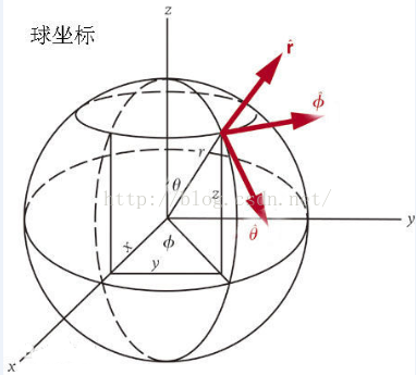 (圖來自百度百科 )
設球上有一點 A ,球心為O ,OA在 xOy上的投影與X軸夾角為φ (范圍為 0 到360 ,單位 :度),
OA在與Z的夾角為θ (范圍為 0 到 180 ,單位:度 ),球的半徑為r,則有 ;
r * sinθ = y / sinφ r * sinθ = x /cosφ z = r * cosθ
由此可得 X,Y,Z坐標
我們前面已經知道,在OpenglES中任何形狀的3D物體都是用三角形來實現了,我們的球自然不能免俗,
那我們該如何用一堆三角形來完成這個球的繪制呢?回想一下我們的圓是怎麼繪制的,對於圓,我們實際繪制的是一個正N邊形,
當N足夠大時我們看起來就是一個圓了,類比一下我們的球也是一樣 :
 當我們分割的足夠多的時候 就像個球了:
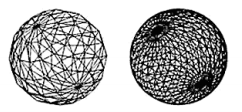
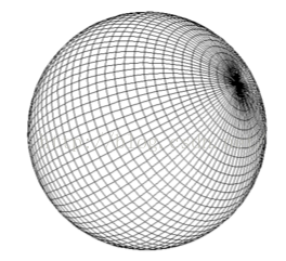 我們實際上是想要繪制這一個個的矩形,我們把其中一個矩形單獨拿來作分析 :
問題一,我們如何確定這個矩形的位置?我們只需要知道這個矩形的左上角的頂點坐標就可以確定該矩形的位置,這個頂點坐標顯然與三個值有關,角度φ (范圍為 0 到360 ,單位 :度) ,角度θ (范圍為 0 到 180 ,單位:度 ),以及球的半徑 r ,r可以是一個固定值 ,因此我們通過雙重循環就可以得到所有的矩形的左上角頂點坐標了。我們先寫一個計算該頂點的代碼 :
public void initVertexData(){
		int angleSpan = 90;//// 將球進行切分的角度
		float r = 0.6f;//球的半徑
		final float UNIT_SIZE = 1.0f;
		for (int vAngle = 0; vAngle < 180; vAngle = vAngle + angleSpan)
		{
			for (int hAngle = 0; hAngle <= 360; hAngle = hAngle + angleSpan)
			{
				float x0 = (float) (r * UNIT_SIZE
						* Math.sin(Math.toRadians(vAngle)) * Math.cos(Math
						.toRadians(hAngle)));
				float y0 = (float) (r * UNIT_SIZE
						* Math.sin(Math.toRadians(vAngle)) * Math.sin(Math
						.toRadians(hAngle)));
				float z0 = (float) (r * UNIT_SIZE * Math.cos(Math
						.toRadians(vAngle)));
			}
		}
	}
每次循環我們都得到一個四邊形的左上角的頂點坐標。我們知道如何求該頂點坐標後,其他三個坐標就很容易求得了,
OK,開始我們畫球計劃正式的第一步 ,我們直接在上節工程的基礎上(我們要用到前面的工具類等,不要從零開始哦 )來做,
在shape目錄下新建一個Ball類 (Ball.java):
package com.cumt.shape;
import java.nio.ByteBuffer;
import java.nio.ByteOrder;
import java.nio.FloatBuffer;
import java.util.ArrayList;
public class Ball {

	private static final float UNIT_SIZE = 1.0f;// 單位尺寸
	private float r = 0.6f; // 球的半徑
	final int angleSpan = 10;// 將球進行單位切分的角度
	private FloatBuffer vertexBuffer;// 頂點坐標
	int vCount = 0;// 頂點個數,先初始化為0
	// float類型的字節數
	private static final int BYTES_PER_FLOAT = 4;
	// 數組中每個頂點的坐標數
	private static final int COORDS_PER_VERTEX = 3;

	public void initVertexData() {
		ArrayList alVertix = new ArrayList();// 存放頂點坐標的ArrayList
		for (int vAngle = 0; vAngle < 180; vAngle = vAngle + angleSpan)// 垂直方向angleSpan度一份
		{
			for (int hAngle = 0; hAngle <= 360; hAngle = hAngle + angleSpan)// 水平方向angleSpan度一份
			{
				// 縱向橫向各到一個角度後計算對應的此點在球面上的坐標
				float x0 = (float) (r * UNIT_SIZE
						* Math.sin(Math.toRadians(vAngle)) * Math.cos(Math
						.toRadians(hAngle)));
				float y0 = (float) (r * UNIT_SIZE
						* Math.sin(Math.toRadians(vAngle)) * Math.sin(Math
						.toRadians(hAngle)));
				float z0 = (float) (r * UNIT_SIZE * Math.cos(Math
						.toRadians(vAngle)));
				// Log.w("x0 y0 z0","" + x0 + "  "+y0+ "  " +z0);

				float x1 = (float) (r * UNIT_SIZE
						* Math.sin(Math.toRadians(vAngle)) * Math.cos(Math
						.toRadians(hAngle + angleSpan)));
				float y1 = (float) (r * UNIT_SIZE
						* Math.sin(Math.toRadians(vAngle)) * Math.sin(Math
						.toRadians(hAngle + angleSpan)));
				float z1 = (float) (r * UNIT_SIZE * Math.cos(Math
						.toRadians(vAngle)));
				// Log.w("x1 y1 z1","" + x1 + "  "+y1+ "  " +z1);

				float x2 = (float) (r * UNIT_SIZE
						* Math.sin(Math.toRadians(vAngle + angleSpan)) * Math
						.cos(Math.toRadians(hAngle + angleSpan)));
				float y2 = (float) (r * UNIT_SIZE
						* Math.sin(Math.toRadians(vAngle + angleSpan)) * Math
						.sin(Math.toRadians(hAngle + angleSpan)));
				float z2 = (float) (r * UNIT_SIZE * Math.cos(Math
						.toRadians(vAngle + angleSpan)));
				// Log.w("x2 y2 z2","" + x2 + "  "+y2+ "  " +z2);
				float x3 = (float) (r * UNIT_SIZE
						* Math.sin(Math.toRadians(vAngle + angleSpan)) * Math
						.cos(Math.toRadians(hAngle)));
				float y3 = (float) (r * UNIT_SIZE
						* Math.sin(Math.toRadians(vAngle + angleSpan)) * Math
						.sin(Math.toRadians(hAngle)));
				float z3 = (float) (r * UNIT_SIZE * Math.cos(Math
						.toRadians(vAngle + angleSpan)));
				// Log.w("x3 y3 z3","" + x3 + "  "+y3+ "  " +z3);
				// 將計算出來的XYZ坐標加入存放頂點坐標的ArrayList
				alVertix.add(x1);
				alVertix.add(y1);
				alVertix.add(z1);
				alVertix.add(x3);
				alVertix.add(y3);
				alVertix.add(z3);
				alVertix.add(x0);
				alVertix.add(y0);
				alVertix.add(z0);

				alVertix.add(x1);
				alVertix.add(y1);
				alVertix.add(z1);
				alVertix.add(x2);
				alVertix.add(y2);
				alVertix.add(z2);
				alVertix.add(x3);
				alVertix.add(y3);
				alVertix.add(z3);
			}
		}
		vCount = alVertix.size() / COORDS_PER_VERTEX;// 頂點的數量
		// 將alVertix中的坐標值轉存到一個float數組中
		float vertices[] = new float[vCount * COORDS_PER_VERTEX];
		for (int i = 0; i < alVertix.size(); i++) {
			vertices[i] = alVertix.get(i);
		}
		vertexBuffer = ByteBuffer
    			.allocateDirect(vertices.length * BYTES_PER_FLOAT)
    			.order(ByteOrder.nativeOrder())
    			.asFloatBuffer();
    	// 把坐標們加入FloatBuffer中
        vertexBuffer.put(vertices);
        // 設置buffer,從第一個坐標開始讀
        vertexBuffer.position(0);
	}
}
我們使用ArrayList來保存頂點坐標,要注意順序的問題,因為我們的四邊形也是由三角形組成的,我們實際上還是繪制兩個三角形。
這六個點應該應該正好組成這兩個三角形。
下面我們來新建頂點著色器和片段著色器,在res / raw 目錄下新建 :
//vertex_shader_ball.glsl
uniform mat4 u_Matrix;//最終的變換矩陣
attribute vec4 a_Position;//頂點位置
void main()
{
    gl_Position = u_Matrix * a_Position;
}
precision mediump float;
void main()
{
   gl_FragColor=vec4(0.2,1.0,0.129,0);
}
接下來和前面一樣,編譯鏈接~~ 等等,此時代碼如下 (Ball.java ):
package com.cumt.shape;

import java.nio.ByteBuffer;
import java.nio.ByteOrder;
import java.nio.FloatBuffer;
import java.util.ArrayList;
import android.content.Context;
import android.opengl.GLES20;
import com.cumt.opengeschange.R;
import com.cumt.utils.MatrixState;
import com.cumt.utils.ShaderHelper;
import com.cumt.utils.TextResourceReader;

public class Ball {

	private Context context;
	private static final float UNIT_SIZE = 1.0f;// 單位尺寸
	private float r = 0.6f; // 球的半徑
	final int angleSpan = 10;// 將球進行單位切分的角度
	private FloatBuffer vertexBuffer;// 頂點坐標
	int vCount = 0;// 頂點個數,先初始化為0
	// float類型的字節數
	private static final int BYTES_PER_FLOAT = 4;
	// 數組中每個頂點的坐標數
	private static final int COORDS_PER_VERTEX = 3;

	private int program;
	private static final String A_POSITION = "a_Position";
	private static final String U_MATRIX = "u_Matrix";
	private int uMatrixLocation;
	private int aPositionLocation;

	public Ball(Context context){
		this.context = context;
		initVertexData();
		getProgram();
		aPositionLocation = GLES20.glGetAttribLocation(program, A_POSITION);
		uMatrixLocation = GLES20.glGetUniformLocation(program, U_MATRIX);
		//---------傳入頂點數據數據
		GLES20.glVertexAttribPointer(aPositionLocation, COORDS_PER_VERTEX,
						GLES20.GL_FLOAT, false, 0, vertexBuffer);
		GLES20.glEnableVertexAttribArray(aPositionLocation);
	}

	public void initVertexData() {
		ArrayList alVertix = new ArrayList();// 存放頂點坐標的ArrayList
		for (int vAngle = 0; vAngle < 180; vAngle = vAngle + angleSpan)// 垂直方向angleSpan度一份
		{
			for (int hAngle = 0; hAngle <= 360; hAngle = hAngle + angleSpan)// 水平方向angleSpan度一份
			{
				// 縱向橫向各到一個角度後計算對應的此點在球面上的坐標
				float x0 = (float) (r * UNIT_SIZE
						* Math.sin(Math.toRadians(vAngle)) * Math.cos(Math
						.toRadians(hAngle)));
				float y0 = (float) (r * UNIT_SIZE
						* Math.sin(Math.toRadians(vAngle)) * Math.sin(Math
						.toRadians(hAngle)));
				float z0 = (float) (r * UNIT_SIZE * Math.cos(Math
						.toRadians(vAngle)));
				// Log.w("x0 y0 z0","" + x0 + "  "+y0+ "  " +z0);

				float x1 = (float) (r * UNIT_SIZE
						* Math.sin(Math.toRadians(vAngle)) * Math.cos(Math
						.toRadians(hAngle + angleSpan)));
				float y1 = (float) (r * UNIT_SIZE
						* Math.sin(Math.toRadians(vAngle)) * Math.sin(Math
						.toRadians(hAngle + angleSpan)));
				float z1 = (float) (r * UNIT_SIZE * Math.cos(Math
						.toRadians(vAngle)));
				// Log.w("x1 y1 z1","" + x1 + "  "+y1+ "  " +z1);

				float x2 = (float) (r * UNIT_SIZE
						* Math.sin(Math.toRadians(vAngle + angleSpan)) * Math
						.cos(Math.toRadians(hAngle + angleSpan)));
				float y2 = (float) (r * UNIT_SIZE
						* Math.sin(Math.toRadians(vAngle + angleSpan)) * Math
						.sin(Math.toRadians(hAngle + angleSpan)));
				float z2 = (float) (r * UNIT_SIZE * Math.cos(Math
						.toRadians(vAngle + angleSpan)));
				// Log.w("x2 y2 z2","" + x2 + "  "+y2+ "  " +z2);
				float x3 = (float) (r * UNIT_SIZE
						* Math.sin(Math.toRadians(vAngle + angleSpan)) * Math
						.cos(Math.toRadians(hAngle)));
				float y3 = (float) (r * UNIT_SIZE
						* Math.sin(Math.toRadians(vAngle + angleSpan)) * Math
						.sin(Math.toRadians(hAngle)));
				float z3 = (float) (r * UNIT_SIZE * Math.cos(Math
						.toRadians(vAngle + angleSpan)));
				// Log.w("x3 y3 z3","" + x3 + "  "+y3+ "  " +z3);
				// 將計算出來的XYZ坐標加入存放頂點坐標的ArrayList
				alVertix.add(x1);
				alVertix.add(y1);
				alVertix.add(z1);
				alVertix.add(x3);
				alVertix.add(y3);
				alVertix.add(z3);
				alVertix.add(x0);
				alVertix.add(y0);
				alVertix.add(z0);

				alVertix.add(x1);
				alVertix.add(y1);
				alVertix.add(z1);
				alVertix.add(x2);
				alVertix.add(y2);
				alVertix.add(z2);
				alVertix.add(x3);
				alVertix.add(y3);
				alVertix.add(z3);
			}
		}
		vCount = alVertix.size() / COORDS_PER_VERTEX;// 頂點的數量
		// 將alVertix中的坐標值轉存到一個float數組中
		float vertices[] = new float[vCount * COORDS_PER_VERTEX];
		for (int i = 0; i < alVertix.size(); i++) {
			vertices[i] = alVertix.get(i);
		}
		vertexBuffer = ByteBuffer
    			.allocateDirect(vertices.length * BYTES_PER_FLOAT)
    			.order(ByteOrder.nativeOrder())
    			.asFloatBuffer();
    	// 把坐標們加入FloatBuffer中
        vertexBuffer.put(vertices);
        // 設置buffer,從第一個坐標開始讀
        vertexBuffer.position(0);
	}

	//獲取program
    private void getProgram(){
    	//獲取頂點著色器文本
    	String vertexShaderSource = TextResourceReader
				.readTextFileFromResource(context, R.raw.vertex_shader_ball);
    	//獲取片段著色器文本
		String fragmentShaderSource = TextResourceReader
				.readTextFileFromResource(context, R.raw.fragment_shader_ball);
		//獲取program的id
		program = ShaderHelper.buildProgram(vertexShaderSource, fragmentShaderSource);
		GLES20.glUseProgram(program);
    }

    public void draw(){
    	//將最終變換矩陣寫入
		GLES20.glUniformMatrix4fv(uMatrixLocation, 1, false, MatrixState.getFinalMatrix(),0);
		GLES20.glDrawArrays(GLES20.GL_TRIANGLES, 0, vCount);
    }
}
然後是在我們的MyRender創建球的對象,並設置攝像機和透視投影並繪制 ,此時代碼如下 (MyRender.java):
package com.cumt.render;

import javax.microedition.khronos.egl.EGLConfig;
import javax.microedition.khronos.opengles.GL10;
import com.cumt.shape.Ball;
import com.cumt.utils.MatrixState;
import android.content.Context;
import android.opengl.GLES20;
import android.opengl.GLSurfaceView.Renderer;
import android.util.Log;
import static android.opengl.GLES20.glClear;
import static android.opengl.GLES20.glClearColor;
import static android.opengl.GLES20.glViewport;

public class MyRender implements Renderer {

	private Context context;

	Ball ball;

	public MyRender(Context context){
		this.context = context;
	}

	public void onSurfaceCreated(GL10 gl, EGLConfig config) {
		Log.w("MyRender","onSurfaceCreated");
		//設置屏幕背景色RGBA
        glClearColor(0.5f,0.5f,0.5f, 1.0f);
		//打開深度檢測
        GLES20.glEnable(GLES20.GL_DEPTH_TEST);
        //打開背面剪裁
        GLES20.glEnable(GLES20.GL_CULL_FACE);
        ball = new Ball(context);
	}

	public void onSurfaceChanged(GL10 gl, int width, int height) {
		glViewport(0,0,width,height);
		float ratio = (float) width / height;
		// 調用此方法計算產生透視投影矩陣
        MatrixState.setProjectFrustum(-ratio,ratio, -1, 1, 20, 100);
		// 調用此方法產生攝像機9參數位置矩陣
     	MatrixState.setCamera(0, 0, 30, 0f, 0f, 0f, 0f, 1.0f, 0.0f);
	}

	public void onDrawFrame(GL10 gl) {
		//清除深度緩沖與顏色緩沖
        glClear( GLES20.GL_DEPTH_BUFFER_BIT | GLES20.GL_COLOR_BUFFER_BIT);
        ball.draw();
	}
}
然後我們來實現通過獲取屏幕點擊事件來旋轉繪制的物體 ,在原來的MySurfaceView中實現該功能 ,如下 (MySurfaceView.java):
package com.cumt.opengeschange;

import com.cumt.render.MyRender;
import com.cumt.utils.MatrixState;
import android.content.Context;
import android.opengl.GLSurfaceView;
import android.view.MotionEvent;
import android.view.View;

public class MySurfaceView extends GLSurfaceView {

	private MyRender myRender;

	public MySurfaceView(Context context) {
		super(context);
		// TODO Auto-generated constructor stub
		myRender = new MyRender(context);
		this.setEGLContextClientVersion(2);
		this.setRenderer(myRender);
		// 設置渲染模式為主動渲染
		this.setRenderMode(GLSurfaceView.RENDERMODE_CONTINUOUSLY);

		this.setOnTouchListener(new OnTouchListener() {

			public boolean onTouch(View v, MotionEvent event) {
				// TODO Auto-generated method stub
				switch (event.getAction()) {
				case MotionEvent.ACTION_DOWN://檢測到點擊事件時
					MatrixState.rotate(20f, 0, 1, 0);//繞y軸旋轉
				}
				return true;
			}
		});
	}
}

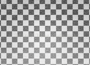 考慮棋盤紋理的繪制策略:
想象一下我們的球是一個立方體切割出來的,這個立方體的邊長就是 2 * r ,r是球的半徑,我們把這個立方體切割成
一個個的小立方體,每個小立方體的位置由其所在的層數,行數和列數共同確定,類比到球的表面,現在球的表面
是一個個分割後的小矩形,每個小矩形的位置由其所在的層數,行數和列數共同確定。假設我們已知分割的層數,
行數和列數都是 n ,一個頂點的坐標是(x ,y,z),求該點所在的層數,行數和列數 ? 求解過程如下 :球的半徑
為 r ,則直徑為 2 * r ,則每個小正方形的邊長為 2 * r / n 。該頂點在Y軸方向坐標為y ,則其距離底層距離為 y + r ,則其所在
層數為 (y + r )/ (2 * r / n ),同理我們求得該點所在行數為 :(x + r )/ (2 * r / n ),所在列數為:(z + r )/ (2 * r / n )。
頂點坐標所在層數,行數,列數三者相加必定是一個奇數或者偶數,如果這三者的和是奇數則該頂點坐在片元顏色設置為
一種顏色,若這三者的和是偶數則該頂點坐在片元顏色設置為另一種顏色,如此就完成了我們的棋盤著色策略。
下面我們來修改一下我們的著色器程序(頂點著色器和片元著色器 ),此時兩者代碼如下 :
//vertex_shader_ball.glsl
uniform mat4 u_Matrix;//最終的變換矩陣
attribute vec4 a_Position;//頂點位置
varying vec4 vPosition;//用於傳遞給片元著色器的頂點位置
void main()
{
    gl_Position = u_Matrix * a_Position;
    vPosition = a_Position;
}
我們在頂點著色器中新加了一個varying vec4 vPosition,用於將頂點數據傳遞給片元著色器,這樣在片元著色器中我們就可以同樣定義一個varying vec4 vPosition來接收頂點著色器傳來的頂點坐標了 。此時片元著色器代碼如下 :
precision mediump float;
varying vec4 vPosition;//接收從頂點著色器過來的頂點位置

void main()
{
   float uR = 0.6;//球的半徑
   vec4 color;
   float n = 8.0;//分為n層n列n行
   float span = 2.0*uR/n;//正方形長度
   //計算行列層數
   int i = int((vPosition.x + uR)/span);//行數
   int j = int((vPosition.y + uR)/span);//層數
   int k = int((vPosition.z + uR)/span);//列數
   int colorType = int(mod(float(i+j+k),2.0));
   if(colorType == 1) {//奇數時為綠色
   		color = vec4(0.2,1.0,0.129,0);
   }
   else {//偶數時為白色
   		color = vec4(1.0,1.0,1.0,0);//白色
   }
   //將計算出的顏色給此片元
   gl_FragColor=color;
}
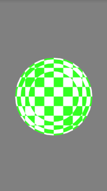 good job !點擊屏幕我們也可以看到球繞Y軸的旋轉了
 HDU 1849 Rabbit and Grass 簡單SG定理
點擊打開鏈接 Rabbit and Grass Time Limit: 1000/1000 MS (Java/Others) Memory Limit: 327
 android:記錄知識點與技巧
去掉ActionBarandroid:theme="@android:style/Theme.Holo.NoActionBar"actionBar =
 Google Play服務已停止運行解決方法
很多朋友在啟動應用或者玩游戲的時候都出現Google Play服務已停止運行,或者之前運行正常的應用突然不能使用了。這是為什麼?在這我們就來講解一下Goog
 [Android Studio] *.jar 與 *.aar 的生成與*.aar導入項目方法
主要講解Android Studio中生成aar文件以及本地方式使用aar文件的方法。 在Android Studio中對一個自己庫進行生成操作時將會同時生成*.jar與